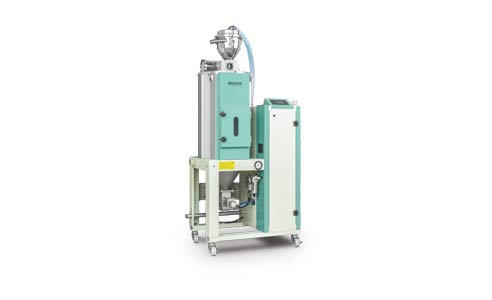
Plastic Dryer
Mold Temperature Controller
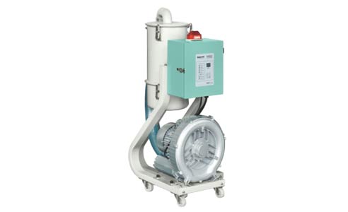
Auto Loader
Plastic Crusher
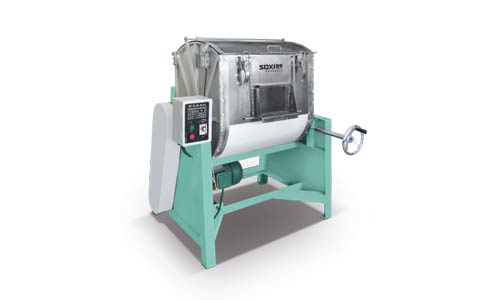
Plastic Mixer
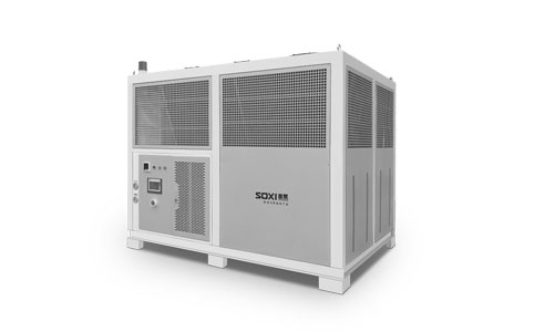
Indusrial Chiller
Automation System
Plastic Machinery Parts
Central Loading System
Central Water Supply System
Power Supply System
Purification System
Central Gas Supply System
Industrial Robot Integration Application
Intelligent Warehouse
Smart Injection Plant Complete Solution
Social activities of Guangdong SOXI Intelligent Equipment Co., Ltd.
Skill competition
Safety production emergency drill
Classification, Working Principles and Precautions for Common Vacuum Hopper Loade
What Are the Methods to Choose an Industrial Chiller?
The Development Trend of Plastic Dryer in the Next Few Years
Characteristics of Dehumidifying Dryer (Standard Type)
What is a Central Conveying System?
The Determinants of Drying Rate of Dehumidifying Dryer Material
The Difference between Dehumidifying Dryer and Ordinary Dryer
What Are the Structural Functions of the Injection Molding Machine?
Introduction to the Principle, Application Range and Characteristics of Hot Air Hopper Dryers
December employee birthday party
Working Principle and Operation of Plastic Moulding Machine
How Can the Mold Temperature Machine Be Cooled?
Classification of Plastic Moulding Machines
The Principle, Use and Classification of Plastic Crusher
How to Choose an Industrial Chiller?
Moulding Method of Plastic Moulding Machine
What is Central Conveying System?
Development Trend of Plastic Dryers in Next Few Years
Plastic Molding Methods for Central Conveying System
Pipeline Layout Requirements and Maintenance Methods of Central Conveying System
Classification, Working Principle and Attention Points of Common Vacuum Hopper Loader
The Difference Between Central Feeding System and Automatic Feeding System
How to Control the Water Volume of the Three-in-one Dehumidification Dryer?
Classification and Selection Skills of Dehumidification Dryers
What Should Be Paid Attention to in the Drying Gas Path of the Dehumidifying Dryer?
Three-in-one Dehumidifier and Dryer Humidity Measurement Method
What is the Function of the Various Accessories of the Dehumidifying Dryer?
What is the Difference Between a Plastic Dehumidifying Dryer and a Dehumidifying Dryer (Standard Type)?
Complete Solution for Central Conveying System
What is the Appropriate Temperature for the Dehumidifying Dryer?
What Do I Need to Do Before a New Dehumidifying Dryer Can Be Used?
Instructions for Use of the Dehumidifier Dryer (Standard Type)
Application Introduction of Industrial Chiller
Dynamic Heat Balance of Mold Temperature Machine: Mold Temperature Control is Essential
Plastic Shredder Machines Play an Important Role in Waste Plastic Recycling
What Details Should Be Paid Attention to when the Central Conveying System Fails?
Maintenance of High-pressure Fans for Central Conveying Systems
What Are the Factors That Affect the Price of Dehumidifying Dryers?
What is the Drying Temperature of the Dehumidifying Dryer?
Three Important Steps to Safely Operate Injection Molding Machines
Five Criteria for Mold Temperature Machine Selection
Why Use a Mold Temperature Machine?
Intelligent Central Conveying System to Help You Realize Intelligent Injection Molding Factory
The Conveying Principle of the Central Conveying System
Automatic Vacuum Hopper Loader is Widely Used in Industrial Development
Fault Detection and Troubleshooting Methods for Dehumidifying Dryer
Choose Dehumidifying Dryer according to Material.
Can Mold Temperature Machine Cool Down?
Drying Process of Dehumidification Dryer
The Application of Dehumidifying Dryer (Standard Type)
Precautions Before Using Dehumidifiying Dryer
Precautions of Using Heat Conducting Oil
Principle and Precautions of Dehumidifying Dryer
The Characteristics of High-pressure Blower with Central Conveying System
Composition of the Central Conveying System
Method of Using Central Conveying System and the Benefits of It‘s’ Installation
Measurement and Precautions of Dehumidification Dryer's Dew Point
How to Choose a High-Quality Central Conveying System?
Introduction to the Application of Industrial Chiller
How to Vent an Industrial Chiller?
Treatment and Functions of Dehumidifying Dryer (Standard Type)
Actual Steps for Using Industrial Chiller Unit
What Types of Dehumidifying Dryer Can Be Classified by Pressure?
Dehumidifying Dryer Dehumidification Mode and Working Principle
Advantages of Central Conveying System Planned for Injection Molding Workshop
Design Process and Characteristics of Central Conveying System
How to Quantify the Central Conveying System?
What Is the Importance of Central Conveying System Components?
What Problems Can the Central Conveying System Solve?
What Are the Reasons That Affect the Effectiveness of Dehumidifying Dryer?
What Are the Advantages of Central Conveying System Compared to Individual Feeding on the Machine?
What Is the Drying Method of Dehumidifying Dryer?
The Differences of Industrial Chiller Performance in Various Environments
Introduction to the Working Principle of a Dehumidifying Dryer (Standard Type)
How to Use the Mold Temperature Machine Correctly?
Search
 English


